Stack Arduino Uno over Raspberry Pi
If you're working on a system that involves both the Raspberry Pi and Arduino Uno, particularly a mobile one, you'll probably want to stack the two boards up vertically. It saves space and in turn, the wiring (arguably) becomes easier. I'll be describing my method for doing this.
Ingredients
(M3 thread size for all)
Base plate to Raspberry Pi
- 2x male/female 6 mm metal spacer
- 2x female/female 6 mm plastic spacer
- 2x metal screw
- 2x plastic screw
Raspberry Pi to Arduino Uno
- 1x male/female 25 mm plastic spacer
- 1x female/female 25 mm metal spacer
- 1x male/female 15 mm metal spacer
- 1x male/female 8 mm metal spacer
- 2x hexagonal metal nut
- 1x hexagonal plastic nut
- 1x metal screw
- 1x 3D printed piece [STL file]
Challenges
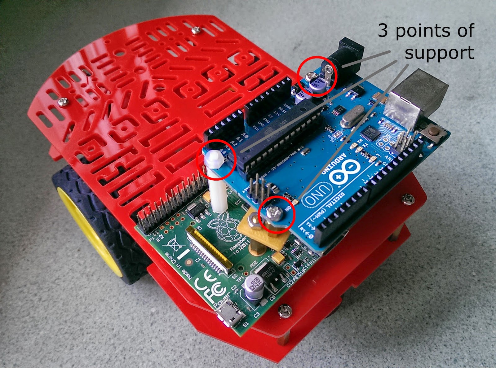
The main challenge relates to the mounting holes of the two boards - the holes of the Raspberry Pi are not aligned with the holes of the Arduino Uno. To solve this, we use a 3D-printed piece to get a spacer that has its two ends slightly offset (see below for details).
The other challenge has to do with the RPi only having two mounting holes. So even if these holes were aligned with two from the Uno, we'll still only have two points of support. That's not ideal. We'll be using a plastic spacer that's secured to the Uno but not secured to the RPi, to get the third point of support.
Recipe
1) Secure four spacers on to the base plate. (Scroll further down for details on the position of the spacers.) Here my base plate is the not-really-recommended Magician's Chassis. Whatever yours may be, you should have four mounting holes on it. You don't want the RPi to be wobbling around when you're wiring up.
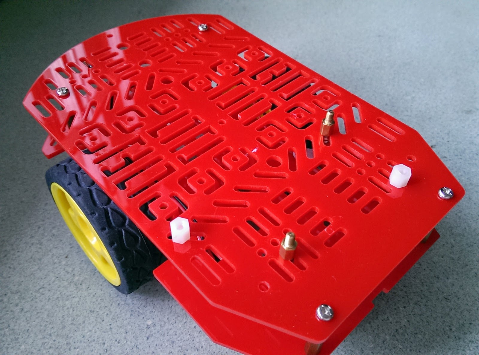 |
| Here's 2x 6mm plastic spacers, 2x 6mm metal spacers, and their respective screws. |
.jpg) |
| The board rests on all four spacers but only the metal ones have mounting holes. |
 |
| The plastic spacer is not secured, actually. It's just standing on the board. |
 |
| And we're done! |
Here we take a closer look at the offset spacer that's in between the two boards. It consists of:
- 1x 3D-printed piece (I call it the cassette tape [Wikipedia])
- 1x metal male/female 15 mm spacer
- 1x metal male/female 8 mm spacer
- 2x hex nut
 |
| Left: offset spacer Right: 3D printed "cassette tape" |
Position of spacers below Raspberry Pi
To provide good support for the Raspberry Pi, I used two plastic spacers in addition to two metal spacers. Just like the 25 mm plastic spacer, these two plastic spacers are also not screwed on to the RPi. They just bear compressive load.
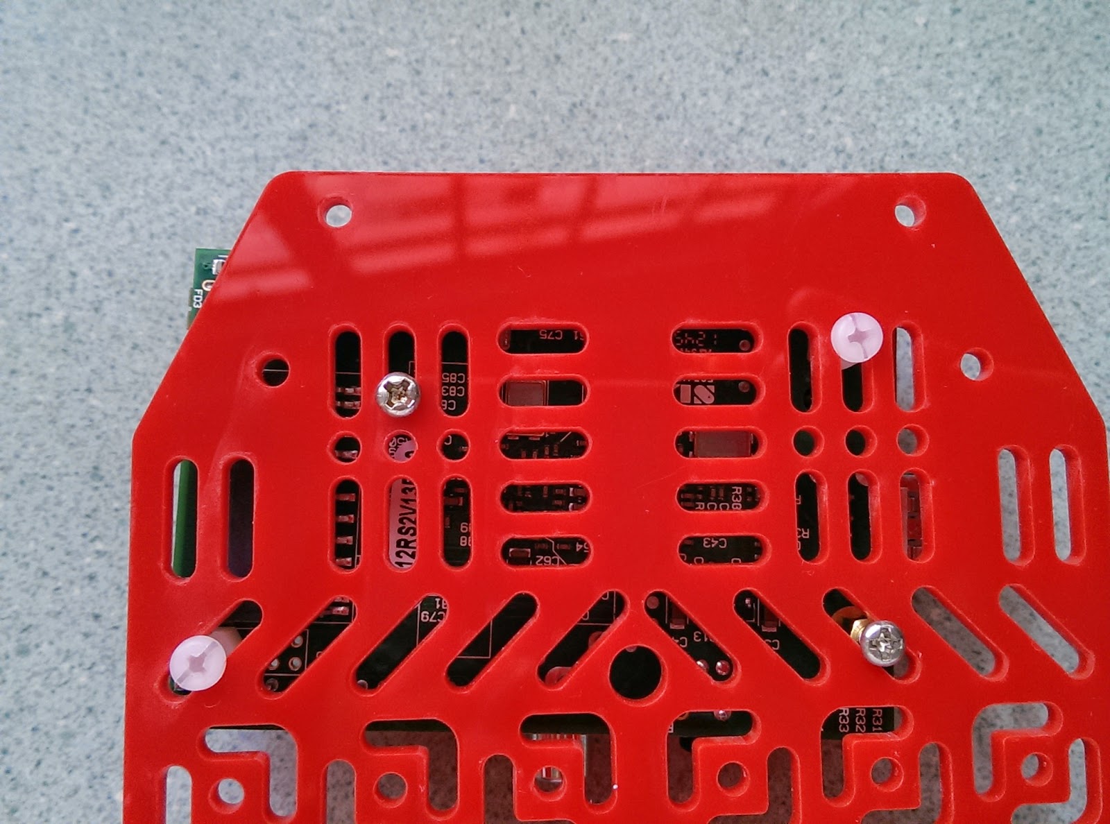 |
| Bottom view of Raspberry Pi attached to base plate |
 |
| Bottom view of Raspberry Pi, with base plate removed. Again, the plastic spacers are just standing there. |
In case you were wondering: yes, it did take a while to find a configuration with which 1) the plastic spacers could sit comfortably on the board and 2) all four spacers were aligned to the holes of the base plate.
Conclusion
OK that may have been a little too elaborate a description. Still, I hope this was helpful. One more thing: if you want a fourth point of contact for your Arduino Uno, you can place a small block between the Uno and the Ethernet port of the RPi. That space on the Uno is smooth and non-conductive. I didn't do this because I didn't need the support there.